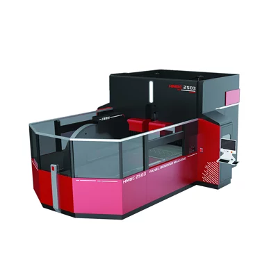
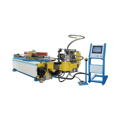
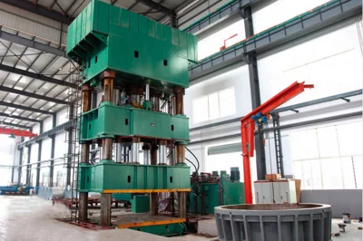
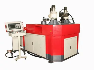
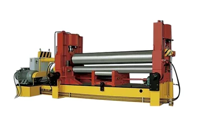
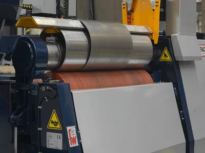
Four Roller Rolling Machine
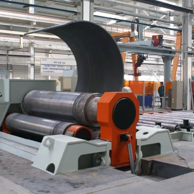
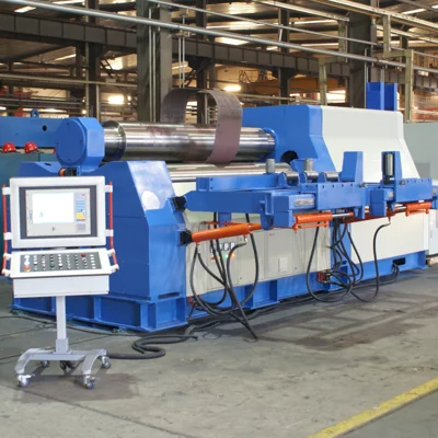
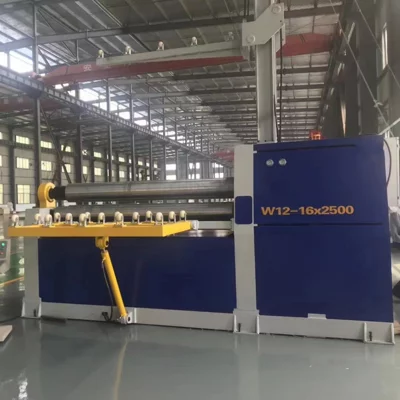
Models List
-
W12-6X2000
-
W12-6X2500
-
W12-8X2000
-
W12-8X2500
-
W12-12*2000
-
W12-12*2500
-
W12-12*3200
-
W12-20*2000
-
W12-25*2000
-
W12-20*2500
-
W12-30*2000
-
W12-25*2500
-
W12-35*2000
-
W12-30*2500
-
W12-40*2000
-
W12-45*2000
-
W12-35*2500
-
W12-40*2500
1 Main structural features
- The four-roller bending machine adopts a torsion-axis synchronous structure, and the four-roller coiling machine has high precision and roundness after being rolled up!
- Full hydraulic motor drive, four-roller coiling machine is environmentally friendly and energy efficient.
- Straight side is short and the pre-bending effect is good! More suitable for roll cones.
- The four-roller reeling process is completed in one pass, including bilateral pre-bending. The four-roller reeling machine is fast, efficient, and easy to operate, requiring only one operator.
- With automatic alignment and clamping function, the plate will not slide and run off.
- The four-roller bending machine has anti-overload and hydraulic protection functions.
- With anti-wear, permanent lubrication-free features.
- The diameter of the reel is small (the four-roll bending machine can roll a cylinder that is less than 1.1 times the diameter of the upper roller, and the linear sliding-guided rolling machine can have a diameter of 1.4-0.5 times the diameter of the upper roller).
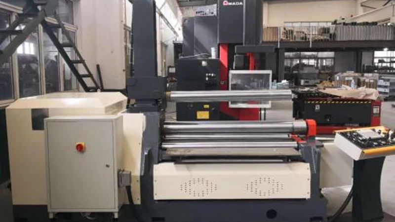
2 Main machine photos
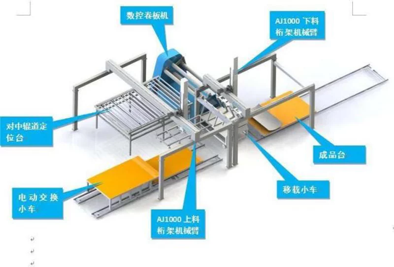
3 Complete line photos
4 Main components list
| Component name | Description | |||
| Bearing | Type | Double-row self-aligning bearing | ||
| Manufacturer | ZWZ Group | |||
| Workingrollers | Material | 42CrMo Forging round HRC50-55 | ||
| Manufacturer | Nanjing Iron and Steel Group | |||
| Frame and chassis | Material | Q235B | ||
| Produce arts | Welded structure, stress handling, Nc boring and | |||
| Manufacturer | SMAC | |||
| Reducer | Type | Planetary reducer | ||
| Manufacturer | EF/ZC | |||
| Hydraulic motor | Type | Radio piston type | ||
| Manufacturer | EF/ZC | |||
| Main electrical component | SIEMENS | |||
| Hydraulic system | Hydraulic pump | Type | Gear pump | |
| Manufacturer | HCHC | |||
| Valve | Manufacturer | NORTHMAN | ||
| Main cylinder | Cylinder body and | 45# steel, heat treatment HRC 48-50 | ||
| Manufacturer | Jiangsu Opu/Jiujiu | |||
| Main cylinder seal | Yx Type | |||
| Manufacturer | Taiwan Dingji | |||
| ControlSystem | Touch screen | SIEMENS | ||
| PLC | SIEMENS | |||
| Encoder and Sensor | OMRON | |||
5 Machine design drawings
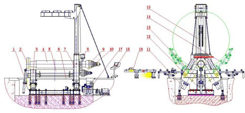
1.Turn-over cylinder 2. headstand 3. left frame 4. upper roller 5. side roller 6. down roller 7. right frame 8. balance 9. upper roller driver device 10. down roller driver device (optional) 11. Side roller cylinder 12. down roller cylinder 13. base 14. side support (optional) 15.top support (optional) 16. feeder roller (optional) 17. hydraulic system 18. electrical system
The Q235 steel plate is adopted as an integral welding structure. The weld seam has undergone strict inspection and post-weld annealing treatment to eliminate internal stress.
The frame and the base are the main force-bearing components of the machine. While the design has sufficient strength and rigidity, it has been further strengthened according to the technological characteristics to ensure the need for coiling. The frame of the welded structure is processed by CNC machine tools to ensure its accuracy.
6 Machine Base
7 Roller
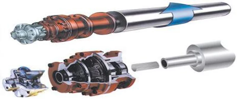
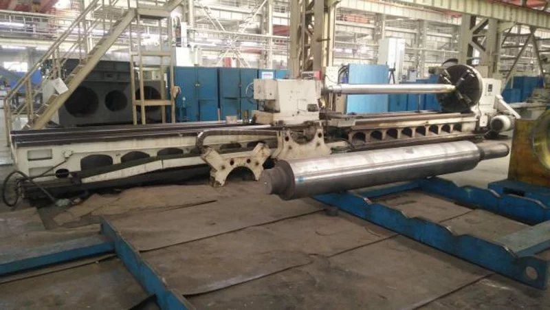
Roller drawings
The roller is more important for the rolling machine, the upper roller and down roller all use 42CrMo forging making. The advantage of this kind of bearing is that no matter where the roller shaft deviates, it can move smoothly and safely along the inclination of the roller shaft, and finally return to its original position. The relative requirements of the tapered coil are much more demanding, because it requires the roller shaft to be able to tilt, and the load on the roller shaft is not balanced. It puts a lot of pressure on the bearing. After adopting the adjustable center bearing, it can make this load enter the "axial" mode, effectively control the influence of folding, and can rotate smoothly and safely. Our company uses two adjustable bearings on each roller shaft and adopts "permanent lubrication technology" throughout the life of the product without frequent lubrication of the bearings.
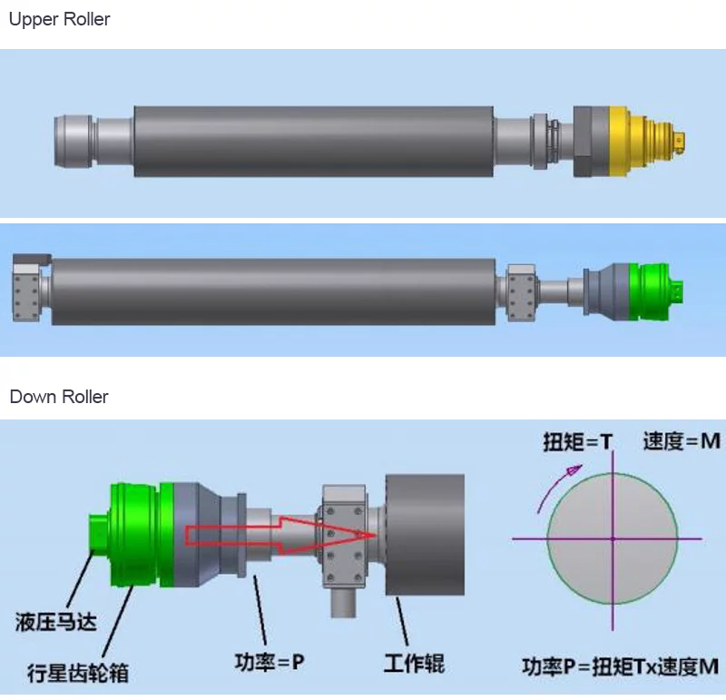
8 Double clamping roller full drive technology

The full drive of the upper and lower rollers ensures that the clamping feed is more stable and accurate. When pre-bending, the edge of the sheet is closer to the clamping point. The shorter the edge of the plate clamped by the upper and lower rollers, the better the pre-bending effect of the plate head, so the full drive of the upper and lower rollers is a necessary condition for obtaining the shortest straight edge length.
9 driving system
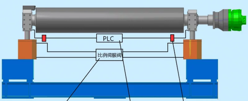
The leveling accuracy at both ends of the bottom roller and side roller directly determines the speed and quality of the coil. In order to better and more conveniently control the leveling accuracy at both ends of the bottom roller and side roller, the leveling accuracy is ±0.1mm. The rollers are controlled by proportional valves.
The feeding platform is mainly set up to cooperate with the rolling operation of the plate rolling machine. There is a vacuum suction cup to transport the sheet to the feeding platform, a set of material alignment device (pneumatic) on the platform will align the sheet to the center, and then the servo motor drives the sheet to feed forward, with precise positioning, and the sheet is rolled after it is in place. Trigger direct clamping and rolling。
10 Main Specification
1、feeder platform width: 2.5m , raw material plate width 700-2500mm; raw material length: 1500-4000mm;
2、feeder platform length : 4.2m;
3、feeder platform height : 750mm;
4、center -self device : 1set (2 group) ;
5、feeder roller material : 35#steel ;
6、platform loading weight: 5000kg;
7、roller diameter: φ120m
8、feeder speed :around 5m/min;
9、feeder power : 1.5kw
The cone rolling device is mainly composed of guide wheel, pin shaft, composite bearing, gland and so on. Its function is mainly to guide the line position when rolling the taper, which is convenient for rolling the taper cylinder, convenient and simple to operate, and reliable to use. It is fixed on the lower roller and moves with the lower roller of the machine.
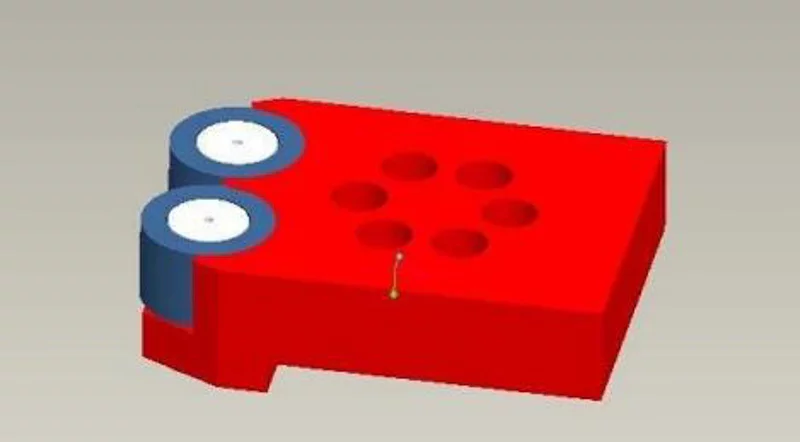
Auto remove rings device: with this device, the finish rolling tank can auto moving to out, easy for operation.
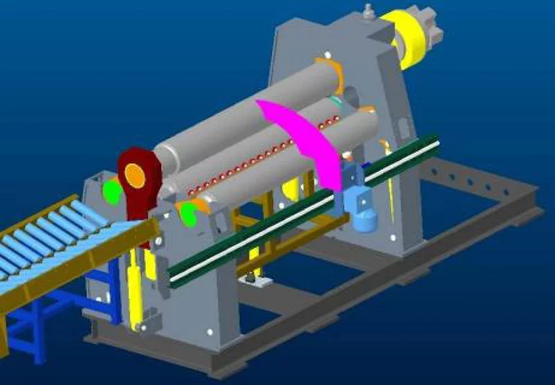
11 Output table
The pushing device pushes the finished product out along the axis of the roller, and adopts an automatic method to avoid the use of traveling vehicles. After the cylinder body is rolled, the lifting device located under the lower roller lifts the cylinder body, and then the pushing device pushes the cylinder body out of the rolling machine.
The whole process is completed automatically, and the cylinder body is prevented from swiping on the work roll during the pushing process after the cylinder body is lifted, which protects the
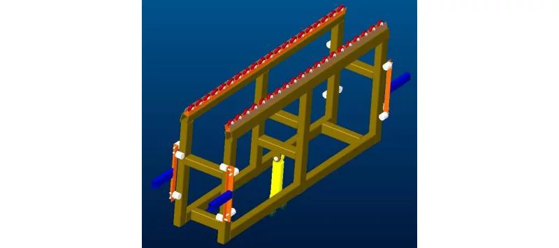
The work roll can also improve the efficiency, avoid the force of the work roll and reduce the discharge resistance. The biggest advantage of this mechanism is that it can hold the arc-shaped workpiece to ensure that the arc-shaped workpiece can be automatically pushed out of the rolling machine.
12 Trolley
The trolley is composed of motor, reducer, transmission mechanism, roller, bracket and other parts.
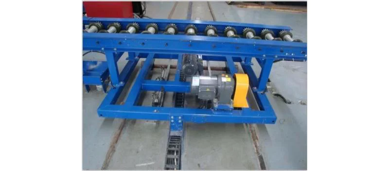
After the workpiece is rolled, the workpiece is pushed out of the rolling machine by the push-out device, and the transfer trolley catches the workpiece outside the machine, and then the drum workpiece is moved to the next station and transported to the next production process. The roller is made of rubber wheel material, which can prevent the workpiece from scratching and shock absorption. The feeding platform device moves smoothly and is easy to use, which greatly improves the overall production efficiency
13 CNC controller
This machine with HIM programming, easy for setting and programming, it is fully CNC line
| Item | W12-6X2000 | W12-6X2500 | W12-8X2000 | W12-8X2500 |
|---|---|---|---|---|
| Max. Thickness mm | 6 | 6 | 8 | 8 |
| Max. Length mm | 2000 | 2500 | 2000 | 2500 |
| Strength Mpa | 245 | 245 | 245 | 245 |
| Rolling Speed m/min | 4 | 4 | 4 | 4 |
| Min. Dia. at Full-load mm | 500 | 600 | 700 | 750 |
| Upper Roller Diameter mm | 250 | 250 | 280 | 300 |
| Lower Roller Diameter mm | 190 | 190 | 260 | 280 |
| Side Roller Diameter mm | 180 | 185 | 180 | 230 |
| Power kW | 5.5 | 7.5 | 11 | 15 |
| Item | W12-12*2000 | W12-12*2500 | W12-12*3200 | W12-20*2000 |
|---|---|---|---|---|
| Max. Thickness mm | 12 | 12 | 12 | 20 |
| Max. Length mm | 2000 | 2500 | 3200 | 2000 |
| Strength Mpa | 245 | 245 | 245 | 245 |
| Rolling Speed m/min | 4 | 4 | 4 | 4 |
| Min. Dia. at Full-load mm | 750 | 750 | 800 | 800 |
| Upper Roller Diameter mm | 300 | 340 | 350 | 350 |
| Lower Roller Diameter mm | 280 | 300 | 320 | 320 |
| Side Roller Diameter mm | 230 | 260 | 240 | 240 |
| Power kW | 18 | 22 | 18 | 18 |
| Item | W12-25*2000 | W12-20*2500 | W12-30*2000 | W12-25*2500 |
|---|---|---|---|---|
| Max. Thickness mm | 25 | 20 | 30 | 25 |
| Max. Length mm | 2000 | 2500 | 2000 | 2500 |
| Strength Mpa | 245 | 245 | 245 | 245 |
| Rolling Speed m/min | 4 | 4 | 4 | 4 |
| Min. Dia. at Full-load mm | 800 | 640 | 1000 | 800 |
| Upper Roller Diameter mm | 350 | 350 | 400 | 400 |
| Lower Roller Diameter mm | 320 | 320 | 360 | 360 |
| Side Roller Diameter mm | 240 | 240 | 240 | 240 |
| Power kW | 22 | 30 | 37 | 37 |
| Item | W12-35*2000 | W12-30*2500 | W12-40*2000 | W12-45*2000 |
|---|---|---|---|---|
| Max. Thickness mm | 35 | 30 | 40 | 45 |
| Max. Length mm | 2000 | 2500 | 2000 | 2000 |
| Strength Mpa | 245 | 245 | 245 | 245 |
| Rolling Speed m/min | 4 | 4 | 4 | 4 |
| Min. Dia. at Full-load mm | 1200 | 1000 | 1400 | 1600 |
| Upper Roller Diameter mm | 420 | 400 | 480 | 500 |
| Lower Roller Diameter mm | 380 | 360 | 400 | 450 |
| Side Roller Diameter mm | 210 | 230 | 420 | 280 |
| Power kW | 37 | 37 | 45 | 45 |
| Item | W12-35*2500 | W12-40*2500 |
|---|---|---|
| Max. Thickness mm | 35 | 40 |
| Max. Length mm | 2500 | 2500 |
| Strength Mpa | 245 | 245 |
| Rolling Speed m/min | 4 | 4 |
| Min. Dia. at Full-load mm | 1200 | 1400 |
| Upper Roller Diameter mm | 480 | 500 |
| Lower Roller Diameter mm | 400 | 450 |
| Side Roller Diameter mm | 420 | 380 |
| Power kW | 45 | 45 |


