Semi-Automatic Working Cycle of Hydraulic System Using on Y27 Hydraulic Press Machine
Share to : 


The hydraulic system's operation can be understood by referring to the appended drawings, hydraulic schematic, and action sequence table. Below is an example of a semi-automatic working cycle:
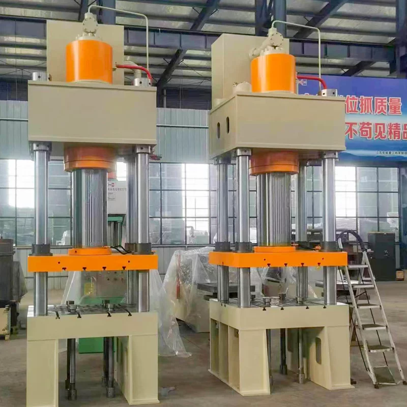
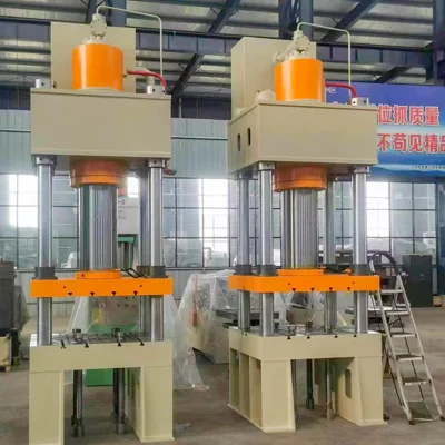
Note: Image of Y27 Hydraulic press Machine
1/Initialization:
Begin by turning on the power and pressing the start button (S82). This activates the motor and the high-pressure axial piston pump. Initially, the pump circulates oil back to the tank through valve 3, operating in an unloaded cycle.
2/System Pressure Setup:
Press the "Hands Run" button, which energizes electromagnets YA1, YA4, and YA5 simultaneously.
- YA1 sets the system to high pressure, regulated by pressure valve 7.
- YA4 and YA5 direct all pump oil into the master cylinder cavity, which opens the hydraulic-controlled check valve, allowing the master cylinder to move downward quickly.
- As the master cylinder descends, negative pressure is created in its upper chamber, causing the liquid valve to open and add oil from the charging cylinder. The oil in the master cylinder then returns to the tank through the check valve, resulting in a rapid descent of the slider.
3/Slow Down for Precision:
When the proximity switch (SQ2) is triggered, it sends a signal that de-energizes YA4 and energizes YA3.
- The oil in the master cylinder now returns to the tank through valve 9, slowing down the slider. This puts the slider in a low-down state, preparing it for precise operation.
4/Pressing and Pressure Maintenance:
As the slider continues to descend, it begins to apply pressure to the product.
- When the pressure reaches the set level, an electrical contact triggers the electromagnet to energize, and the time relay (KT1) is activated.
- The slider enters a packing delay state. Once the delay time set by KT1 is reached, electromagnets YA2, YA9, and YA6 are energized, reducing the system to low voltage.
- YA9 controls the opening of the filling valve control port, allowing high-pressure oil in the upper cylinder to be relieved.
- The system remains in a relief state, monitored by the time relay (KT2).
5/Return to Start Position:
After the relief time set by KT2 ends, the system returns to normal operation.
- YA6 de-energizes, and YA1 and YA9 are energized, directing system oil into the cylinder, allowing oil in the upper master cylinder to return to the tank.
- This causes the slider to return quickly to its starting position.
6/Ejection Phase:
When the proximity switch (SQ3) is triggered, YA1, YA7, and another electromagnet (YA?) are energized.
- System oil flows through valve 2 into the lower chamber of the top cylinder, initiating ejection.
- As the slider returns to the proximity switch (SO1), the top cylinder continues ejection until it triggers the proximity switch (SQ4), at which point ejection stops.
- Simultaneously, time relay KT3 is activated, putting the system into an ejection delay state.
7/Cycle Completion:
Once the ejection delay time set by KT3 ends, YA1 and YA8 are energized, causing system oil to flow through valve 3 into the return chamber of the top cylinder.
- The top cylinder then returns to its starting position.
- When the proximity switch (SQ5) is triggered, all actions stop, completing the process cycle.
With years of hands-on experience, I have honed my skills in navigating the complexities of global commerce, offering invaluable insights and solutions to address customer needs. My commitment to excellence and dedication to customer satisfaction ensure that I deliver exceptional service, guiding clients through every step of the trading process with confidence and proficiency.