Introduction of Y27 Hydraulic Press Machine Structure

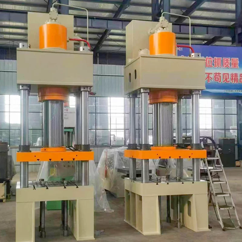
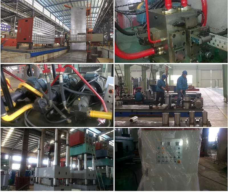
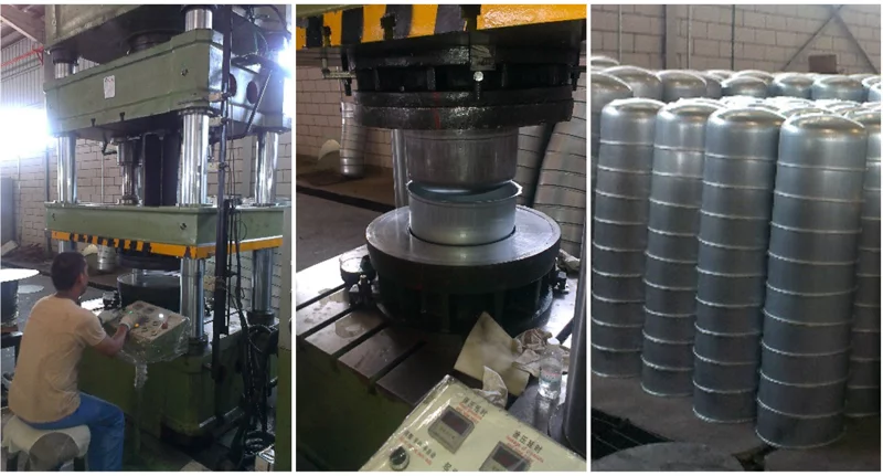
Y27 Hydraulic Press Machine is main made up of mainframe and control system, through piping and electrical device linked to form a whole. Host consists of fuselage, master cylinder, cylinder, hydraulic cushion of pack out and filling liquid equipment etc. Control system including hydraulic pump station (power system), electrical box, and control console. Bellowing is the structure and function of each part points mentioned:

1, The Fuselage (see the machine appearance drawings)
The fuselage is made up of top beam, table, slider, support, hydraulic cushion, lock nut and screw nut and so on, relay on four columns as support, beam and table fixed by the lock nut is at the both ends, slider is fixed between the top beam and the table, the precision of the machine is adjusted by the adjusting nut and the locknut fixed on the top beam. The slider and the master cylinder piston rod are connected with flange connection, rely poster for guiding and down movement, slider and table both have T-shaped slot; in order to mold installation, which size is in the drawing. (Note: This installation tool must be used to connect standard T-block, or T-slot is damaged at your peril.)

2, Master Cylinder
a double-cylinder structure, arranged in the upper beam, cylinder flange and the upper beam is fixed with the piston rod connected through the connection flange and activities beams. Cylinder material quality 45 # forged steel, to ensure uniform material; The piston head has an outer ring at the opposite direction, there is "O"-ring seal in and the cylinder forming the upper and lower oil chamber. Cylinder adopts imported sealing elements to ensure reliable sealing performance, no leakage, easy maintenance.
3, Additional Table
There are T-slots and ejector holes on the additional table, random with 10 plungers.
4, Hydraulic Cushion
Hydraulic cushion is within the table as welding parts. Hydraulic cushion stroke can be adjusted within a certain range, hydraulic cushion is guided by four pillars, it equipped with a plunger mat in order to prevent the hydraulic cushion deformation and damage.
5, Locking Device
When the slider runs to the upper limit position, the locking mechanism is automatically inserted to prevent accidental slide down, to ensure operator safety.
6, Ejection Cylinder
Ejection cylinder is equipped in the table hole, fixed with a locking nut, its structure is similar to the master cylinder.
7, Work Station
Work station can move freely within a certain range, there are buttons, time relays on the box face.
8, Stroke Limit Device
Stroke limit device is at the right side of the machine, by the holder, hit the block, proximity switches and other components, support at both ends fixed on the right of the table and the top beam, on the supports approaching the switch, you can adjust the slider switch position to adjust the slider.
9, Hydraulic Pump Station (power system)
Hydraulic pump station is made up of tank, motors, valves and other components. Tank built with filters, it used oil standard in the front to observe the oil level, oil height should upper the oil standard, if less that needs to add.
With years of hands-on experience, I have honed my skills in navigating the complexities of global commerce, offering invaluable insights and solutions to address customer needs. My commitment to excellence and dedication to customer satisfaction ensure that I deliver exceptional service, guiding clients through every step of the trading process with confidence and proficiency.


